
Figure
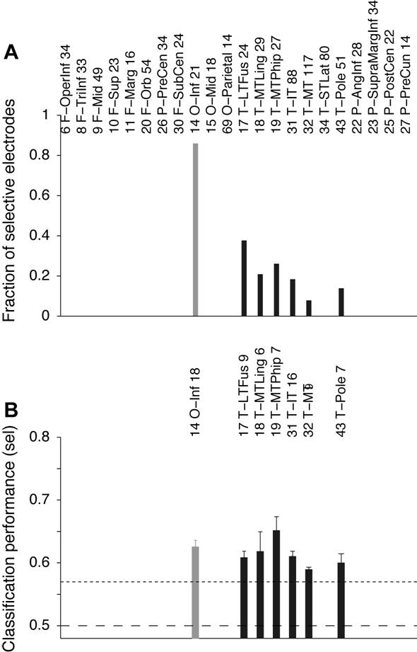
S12: Location of individual electrodes showing selectivity
A. Fraction of electrodes that showed selectivity in each area
where we recorded from at least 10 electrodes. The location of each electrode
is based on co-registering the MR and CT scans for each subject (see Figure
S11, Table S2 and Supplementary Material). The number before each location
abbreviation indicates the “area code” within the parcellation maps in (Desikan
et al., 2006) (Table S2). Locations in the occipital lobe have are depicted
with gray bars and locations in the temporal lobe are depicted with a black
bar. Here and throughout the manuscript, locations in the right and left
hemisphere were pooled together. B. Mean
classification performance for each location. Error bars indicate SEM. The dashed
horizontal line shows chance performance (0.5) and the dotted line shows the
selectivity threshold (see Figure S5).